Design and Evaluation of a Bending Actuator for a Robotic Uterine Manipulator, based on a McKibben Pneumatic Artificial Muscle
Abstract
A bending actuator for a robotic uterine manipulator was designed and evaluated. The actuator is based on a McKibben pneumatic artificial muscle (PAM) and aimed to reduce the surgeon’s operating time and lower the risk of patient injury. To enable the operation to be conducted using a laparoscope, the manipulator had to be able to manipulate the uterus in two degrees of freedom (2-DOF) with a minimum bending angle of ±45° and force of 3 N. Considering these requirements, three PAMs were placed using two disks at 120° intervals to manipulate the uterus in 2-DOF by pressurizing them. A kinematic model of the manipulator was derived and its workspace was computed. Based on this result, the manipulator was fabricated and its bending angle and tip force experimentally evaluated. We successfully demonstrated that the uterus could be controlled with a tip force of 3.31 N at a bending angle of 50°.
Keywords:
Manipulator, Robotics, Pneumatic, Bending actuator, Medical robot1. Introduction
Among women’s diseases, the prevalence of uterine cancer and cervical cancer has increased. Accordingly, the demand for laparoscopic surgery has also increased because it’s less invasive and offers faster recovery times. It is the predominant surgical technique used in obstetrics and gynecology, and its specific applications include ectopic pregnancy, removal of uterine myoma, monitoring lymph node dissection, and uterine cancer. In surgically treating uterine cancer, a uterine manipulator is used to control the position and orientation of the uterus, ensuring the surgeon has a clear field of view during surgery. However, there are some problems with operating uterine manipulators during surgery: since the manipulators are manually operated, an additional medical assistant is required to operate them. Because this assistant receives directions from the surgeon and must accurately make manipulations in real time, there’s a higher potential for miscommunication, operator fatigue, and accidents.
Some uterine manipulators are used in surgery these days,[1-3] but because their movement is limited to a single plane, there can be inaccurate movement and manipulation. Although Serkan Dikici et al. proposed a parallel uterine manipulator with two degrees of freedom(2-DOF)[4], it still required manual manipulation by an additional medical assistant. Hiu Man Yip et al. designed a 3-DOF robotic uterine positioner[5], which does not require an additional medical assistant. However, it is operated from outside the human body and its rigid structure had the potential to cause damage to the human body. To prevent or reduce injury, a manipulator with a flexible structure should be considered.
Therefore, this project proposes a robotic uterine manipulator which utilizes McKibben pneumatic artificial muscle (PAM) and incorporates 2-DOF flexible bending motion[6-10]. It allows the surgeon to directly manipulate the uterus during the procedure and maintain its position without an assistant. To improve device flexibility and help prevent injury to the patient’s vagina and cervix, three McKibben pneumatic artificial muscles (PAMs) are used in an actuator which is capable of 2-DOF bending motion. This actuator allows flexible control of the uterine manipulator in 2-DOF by individually pressurizing either one or two PAMs in opposition along the length of the actuator. The proposed manipulator also includes a linear servo motor which controls fore/aft translation, resulting in a device with 3-DOF manipulation capabilities. The kinematic modeling of the manipulator is derived according to a constant curvature model. The PAMs function like tendons, and according to workspace computations, either lengthen or shorten to achieve the desired position. This computed position is compared with the actual movement of the manipulator using video tracking to confirm the modeling accuracy. Minimum design criteria were established to effectively manipulate the uterus, which included a bending angle of (± 45°) and a force (3 N)[11], and this bending angle and tip force were evaluated experimentally.
2. Design of the Robotic Uterine Manipulator
2.1 Requirements for the Manipulator
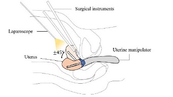
In order to develop a uterine manipulator for laparoscopic surgery, it is necessary to comprehend the surgical procedure and female reproductive system. In laparoscopic surgery such as uterine cancer surgery, the surgeon checks the internal conditions of the patient through a camera. During the entire surgical procedure, the uterus is continuously manipulated by a separate assistant with a uterine manipulator. The manipulator is inserted through the patient’s vagina up to the cervix, the cup seats on the cervix, and the tip extends through the cup into the uterus. To operate via the vagina, the manipulator design size should accommodate the dimensions of a human vagina. Accordingly, the average vagina length is 62.7 mm, within a large range (40.8-95 mm), and the narrowest diameter is 26.15 mm[12]. The uterus has a mass of 270 g on average, and the manipulation angle range should be ± 45° during surgery as shown in Fig. 1. Since previously developed uterine manipulators require communication between the surgeon and staff, the control process is inefficient and, and it requires more of the surgeon’s valuable time to coordinate. Moreover, the conventional uterine manipulators have a rigid structure and may cause damage to the human body. In order to overcome the aforementioned limitations, a robotic uterine manipulator could be designed to satisfy the following requirements.
- 1. Have a flexible structure with smooth bending movement to prevent injury.
- 2. The manipulator should be able to control the uterus position at an angle of ± 45° in 2-DOF
- 3. To lift and control the uterus, the tip of the manipulator must generate sufficient force.
2.2 Configuration of the Manipulator
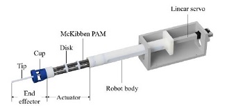
The proposed robotic uterine manipulator consists of a series of PAMs that create bending movement and a linear servo motor which controls fore/aft translation. The configuration is shown in Fig. 2. The actuator consists of a series of three segments of McKibben PAMs separated by two 4 mm-thick disks, spaced equally. Each segment consists of three PAMs placed radially at 120° intervals around the circumference of the disks. The diameter of the disks and end effector is 25 mm, which is smaller than the vagina. Each PAM is located 8 mm from the center of each disk and the ends pass through an 8 mm diameter hole in the disks. The cup and tip are attached to the end of the actuator, which includes an end-effector, which fixes the manipulator to the uterus. Since translational movement is necessary during surgery, a linear servo motor (L-12R, Fergelli) is installed in the manipulator to allow 100 mm fore/aft translational movement of the uterus.
2.3 McKibben Pneumatic Artificial Muscle
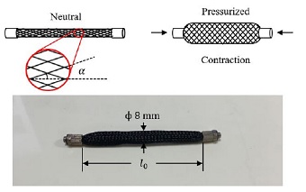
The McKibben PAM is a popular artificial muscle device due to its superior properties, and a schematic diagram of the McKibben PAM is shown in Fig. 3. The McKibben PAM is composed of an inflatable rubber tube inside a braided mesh. They are attached to pneumatic fittings (LCN-0640-M5, PISCO) at each end. One end is capped and the other is connected to the air supply. When the rubber tube is pressurized with air, it expands radially and contracts longitudinally until the braided angle of the mesh reaches its designed limit. The PAM contraction occurs when the braided angle α is less than 54.7°. The contraction ratio of every McKibben PAM is different but does not exceed 35%[13]. In this study, braided mesh with a diameter of 8 mm are used, and their specifications are shown in Table 1. With a simple PAM experiment, a contraction ratio of 25% is measured with 0.6 MPa of internal air pressure.
| (1) |
where l0 denotes initial PAM length and l denotes contracted length.
3. Kinematic model of the Manipulator
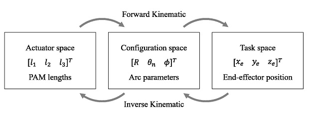
The actuator is bent to specific angles by pressurizing and depressurizing each PAM individually. Since it is difficult to derive a model with infinite degrees of freedom, a kinematic model of constant curvature is used in this section. To apply this model to the proposed manipulator, it is assumed that each PAM of the actuator behaves like a tendon when it is pressurized. The constant curvature kinematic model is divided into three spaces and two mappings that link the spaces and states as shown in Fig. 4. The actuator space consists of the length of the series of PAMs. The configuration space is composed of independent variables, arc parameters, that determine the robot’s posture. Task space refers to the space in which the actual robot object moves.
Since the actuator is composed of three segments in series, a general model of one segment is computed, and this model is applied to the three segments, determining the movement of the overall actuator.
3.1 Mapping between Actuator Space and Configuration space
The objective of mapping between actuator space and configuration space is to derive the relationship between PAM lengths (l1,l2,l3) and arc parameters (R,θn,ϕ) of the constant curvature model.
The bending actuator is divided by disks spaced equally apart as shown in Fig. 5. To express the bending angle, the thickness of the disk is ignored. Instead, the calculated length of the PAM is reduced by the total thickness of the disks. The radius of curvature of a segment(R) is derived as follows[14].
| (2) |
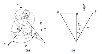
(a) Configuration of an actuator segment. (b) Diagram of the section to determine the bending angle θ
where d is the radial distance between the PAM and center of the disk, and li is the length of the ith PAM in a segment. Also, the rotation angle of the actuator(ϕ) is derived as
| (3) |
The bending angle of a segment(θn) is expressed by the curvature radius of each segment(R) and the length of an imaginary centerline of the segment(lc), which is expressed as
| (4) |
where
| (5) |
3.2 Mapping between Configuration space and Task space
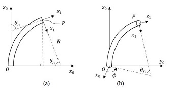
To obtain relationship between configuration space and task space, a homogeneous transformation matrix is used. It is assumed the + z0 axis of the base coordinate to be tangent to the base of the segment.
When the rotation angle of the segment(ϕ) is 0, the bending direction of the segment defines the + x0 axis, and + y0 axis is defined by right-hand rule, as shown in Fig. 6. In this situation, the actuator lies in the x-z plane, and bends with a constant radius of curvature(R) at a bending angle of a segment(θn). The position of the end point of a segment(P) is expressed as:
| (6) |
If we rotate the segment at an angle of ϕ about + z0 axis, the homogenous transformation matrix can be derived as follows[15].
| (7) |
where Rz and Ry represent rotation matrix about +z axis and +y axis respectively. To consider the thickness of the disks, translational matrix A is considered.
| (8) |
where t in matrix A denotes the disk thickness of 4 mm. Post-multiplying T by A can represent (i-1)th segment coordinate system, expressed as:
| (9) |
where c and s represent cos and sin respectively. Since the actuator is composed of three segments in series, the position of the end of the actuator and orientation can be computed as:
| (10) |
and position of end of the actuator is
| (11) |
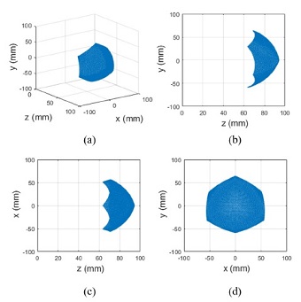
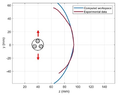
where the workspace of the 2-DOF bending actuator can be derived and is shown in Fig. 7. The initial lengths of the PAM in a segment(l1,l2,l3) are 27.33 mm, because of thickness (t) of two disks. At a 25 % contraction ratio with 0.6 MPa of internal air pressure, the maximum decreased length is 20.5 mm. The workspace is computed with decreasing the length of two PAMs. Decreasing all three PAMs prevents it from bending. It shows that the workspace is symmetric about the y-z plane and has order 3 rotational symmetry when viewed from the x-y plane, which is the front of the manipulator. The workspace of the manipulator would vary with a different sized end-effector, cup and tip.
4. Experiments and Discussion
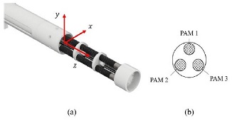
The coordinate system of the manipulator and position of PAMs are shown in Fig. 8. Three experiments are conducted to evaluate whether the manipulator can be used as a uterine manipulator. Since the performance of the manipulator depends on the tip and cup size, experiments are conducted without the end-effector, which is comprised of the tip and cup.
- 1. Workspace: Confirm the movement of the manipulator and compare it with the value derived through kinematic modeling.
- 2. Bending angle: Measure the bending angle according to pressure. Make sure the manipulator's bending angle can cover the minimum angle required to manipulate the uterus.
- 3. Tip force: Measure tip force according to internal pressure. Also, confirm that the uterus can be lifted by measuring the maximum force according to the angle.
Although the proposed manipulator can be a good alternative that does not cause injury, it has a limitation. Since PAMs have low stiffness, the actuator can show buckling[16]. However, in this paper, the kinematic modeling is carried out under the assumption that the PAMs should show a tendon-like behavior, which maintains their shape. According to experiments of Qin Tu et al.[17], the contraction of the PAM showed when the internal pressure is higher than 0.15 MPa. Therefore, all experiments are premised on applying a basic pressure of 0.15 MPa to three PAMs.
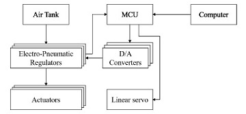
The control system configuration is shown in Fig. 9. Three Electro-Pneumatic (EP) regulators are used to supply the desired pressure to the individual PAMs. The micro-controller unit (MCU) sends the desired pressure of the PAMs to the EP regulators (ITV0050, SMC) through D/A convertors. Since the EP-regulator is designed to maintain constant pressure if the power is suddenly cut off, the normally closed 3 port valve (LVMK207, SMC) allows the air in the PAMs to exhaust when the power is turned off. For linear motion, a PWM signal (1~2 ms) is transmitted from the MCU to the linear servo motor in the manipulator.
4.1 Workspace
To evaluate accuracy of the proposed kinematic model, computed workspace data from section 3.2 is compared with experimental position data of the actuator end and is shown in Fig. 10. The computed workspace is drawn with points where x coordinates are set at 0, and to compare, a video tracking method is utilized. The upper bending motion can be generated by pressurizing PAM 1 in Fig. 8(b), and downward movement is generated by pressurizing PAM 2 and PAM 3 at the same time. It shows larger positional errors as it moves away from the center, and the maximum deviation is measured at 17.65 mm. In addition, pressurizing two PAMs, which generates downward bending motion, generates more errors because of interference between two contracted PAMs. It affects the reduction of the contraction ratio[18] and it is directly related to the workspace of the manipulator. It can be said that the error comes from a combination of modeling assumptions, the low stiffness of the actuator, and measurement errors.
4.2 Bending Angle
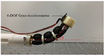
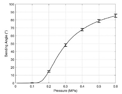
The bending angle experiment was performed only in +y axis by pressurizing only PAM 1. The experimental configuration for the bending angle measurement and definition of bending angle of the manipulatorθ is shown in Fig. 11. The bending angle was measured with a 6-DOF gyro-accelerometer sensor (GY-521, HiLetgo) mounted on the top of the end-effector. The internal pressure was set from 0 to 0.6 MPa and the experiment was conducted 10 times.
The experimental results of bending angle measurement is shown in Fig. 12. The maximum bending angle of the manipulator was 85.3 ± 2.02° with 0.6 MPa of internal pressure.
4.3 Tip Force according to Internal Pressure
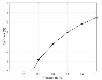
To measure the force generated from the manipulator, a blocked force test is conducted, and the test configuration is shown in Fig. 13. The manipulator is mounted on the platform and the load cell (CB1-K5, DACELL), which contacts the end of the actuator, is installed on a rotatable stage. Tip force is measured only in the +y direction to confirm that the manipulator generates enough force to lift and control the uterus. Since the mean weight of the uterus is 270 g, the actuator must generate at least 3 N. The rotatable stage fixed the load cell at 0° and the internal pressure of the PAM is increased from 0 to 0.6 MPa.
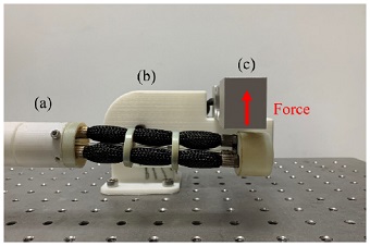
Configuration of tip force measurement. The stage for the load cell is set to 0°. (a) manipulator (b) rotatable stage (c) load cell
The experimental results are shown in Fig. 14. These results confirm that the manipulator generates maximum 5.45 ± 0.02 N on the tip with 0.6 MPa of internal pressure.
4.4 Tip Force according to Bending angle
To measure the tip force for different bending angles of the manipulator, the load cell is rotated to 0° on the stage and the actuator engaged the load cell as shown in Fig. 15. The maximum applied pressure is 0.6 MPa.
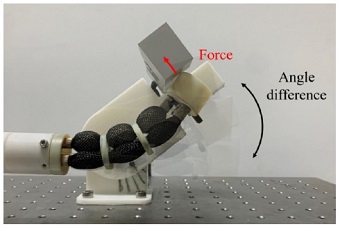
Tip force measurement for different angles. The load cell rotates on the stage as pressure is increased from 0 to 0.6 MPa to measure the maximum force at the tip
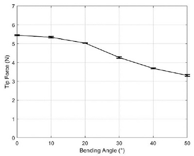
The experimental results of tip force measurements for different actuator bending angles is shown in Fig. 16. The actuator generated 3.31 ± 0.05 N of tip force at 50° of bending angle, and a smaller bending angle generated a higher tip force.
5. Conclusions
In this paper, a 2-DOF uterine manipulator based on PAM actuators is designed and evaluated. Three key points are considered; a flexible structure, 2-DOF manipulation, and adequate force to control the uterus. A constant curvature model was used to derive the kinematic model and was compared with actual movement. To adequately manipulate the uterus in surgery, a minimal bending angle of (± 45°) and force (3 N) are required. Through experiments, it was shown that the manipulator can control the uterus up to 85.3 ± 2.02° of bending angle under 0.6 MPa of internal pressure. In addition, 3.31 ± 0.05 N of tip force at 50° of bending angle was measured, which increased to 5.45 ± 0.02 N as the bending angle decreased towards 0°.
The advantages of using this manipulator are that it has a flexible structure which can help prevent injury, and unlike manually operated uterine manipulators, it generates 2-DOF motion without rotation. Using the simple working principle of pressurized PAMs, it satisfies the requirements necessary to manipulate the uterus in surgery. In future work, a real-time feedback control strategy will be studied.
Acknowledgments
This research was supported by a grant of the Korea Health Technology R&D Project through the Korea Health Industry Development Institute (KHIDI), funded by the Ministry of Health & Welfare, Republic of Korea (grant number: HI19C0664).
References
-
Van den Haak, L., Alleblas, C., Nieboer, T. E., Rhemrev, J. P., Jansen, F. W., 2015, Efficacy and Safety of Uterine Manipulators in Laparoscopic Surgery: A Review, Archives of Gynecology and Obstetrics, 292:5 1003-1011.
[https://doi.org/10.1007/s00404-015-3727-9]

-
Mettler, L., Nikam, Y. A., 2006, A Comparative Survey of Various Uterine Manipulators used in Operative Laparoscopy, Gynecol Surgery, 3:4 239-243.
[https://doi.org/10.1007/s10397-006-0215-z]

-
Khalek, A. Y., Bitar, R., Christoforou, C. Garzon, S., Tropea, A., Biondi, A., Sleiman, Z., 2019, Uterine Manipulator in Total Laparoscopic Hysterectomy: Safety and Usefulness Updates in Surgery, 1-8.
[https://doi.org/10.1007/s13304-019-00681-w]

-
Dikici, S., Aldemir Dikici, B., Eser, H., Gezgin, E., Başer, Ö., Şahin, S., Yılmaz, B., Oflaz, H., 2015, Development of a 2-dof Uterine Manipulator with LED Illumination System as a New Transvaginal Uterus Amputation Device for Gynecological Surgeries, Minimally Invasive Therapy & Allied Technologies, 27:3 177-185.
[https://doi.org/10.1080/13645706.2017.1341927]

-
Yip, H. M., Wang, Z., Navarro-Alarcon, D., Li, P., Liu, Y., Cheung, T. H., 2015, A New Robotic Uterine Positioner for Laparoscopic Hysterectomy with Passive Safety Mechanisms: Design and experiments, IEEE/RSJ International Conference on Intelligent Robots and Systems (IROS), 3188-3194.
[https://doi.org/10.1109/IROS.2015.7353819]

-
Al-Ibadi, A., Nefti-Meziani, S., Davis, S., 2018, Design, Implementation and Modelling of the Single and Multiple Extensor Pneumatic Muscle Actuators, Systems Science & Control Engineering, 6:1 80-89.
[https://doi.org/10.1080/21642583.2018.1451787]

-
Al-Ibadi, A., Nefti-Meziani, S., Davis, S., 2017, Efficient Structure-Based Models for the McKibben Contraction Pneumatic Muscle Actuator: The Full Description of the Behavior of the Contraction PMA, Actuators, 6:4 32.
[https://doi.org/10.3390/act6040032]

-
Al-Ibadi, A., Nefti-Meziani, S., Davis, S., 2016, Valuable Experimental Model of Contraction Pneumatic Muscle Actuator, 21st International Conference on Methods and Models in Automation and Robotics (MMAR), 744-749.
[https://doi.org/10.1109/MMAR.2016.7575229]

-
Peng, Y., Liu, Y., Yang, Y., Liu, N., Sun, Y., Liu, Y., Pu, H., Xie, S., Luo, J., 2019, Development of Continuum Manipulator Actuated by Thin McKibben Pneumatic Artificial Muscle, Mechatronics, 60 56-65.
[https://doi.org/10.1016/j.mechatronics.2019.05.001]

-
De Volder, M., Moers A. J. M., Reynaerts, D., 2011, Fabrication and Control of Miniature McKibben Actuators, Sensors and Actuators A: Physical, 166:1 111-116.
[https://doi.org/10.1016/j.sna.2011.01.002]

-
Louie, M., Strassle, P. D., Moulder, J.K., Dizon, A. M., Schiff, L. D., Carey, E. T., 2018, Uterine Weight and Complications After Abdominal, Laparoscopic, and Vaginal Hysterectomy, American Journal of Obstetrics and Gynecology, 219:5 480.e1-480.e8.
[https://doi.org/10.1016/j.ajog.2018.06.015]

-
Barnhart, K. T., Izquierdo, A., Pretorius, E. S., Shera, D. M., Shabbout, M., Shaunik. A., 2006, Baseline Dimensions of the Human Vagina, Human Reproduction, 21:6 1618-1622.
[https://doi.org/10.1093/humrep/del022]

-
Al-Ibadi, A., Nefti-Meziani, S., Davis, S., Theodoridis, T., 2018, Novel Design and Position Control Strategy of a Soft Robot Arm, Robotics, 7:4 72.
[https://doi.org/10.3390/robotics7040072]

-
Lee, D. K., Joe, S. G., Choi, J. W., Lee, B. I., Kim, B. K., 2016, An Elastic Caterpillar-based Self-propelled Robotic Colonoscope with High Safety and Mobility, Mechatronics, 39 54-62.
[https://doi.org/10.1016/j.mechatronics.2016.08.002]

-
Hannan, M. W., Walker, I. D, 2003, Kinematics and the Implementation of an Elephant’s Trunk Manipulator and Other Continuum Style Robots, Journal of Robotic System, 20:2 45-63.
[https://doi.org/10.1002/rob.10070]

-
Tschiersky, M., Hekman, E. E. G., Brouwer, D., Herder, J., Suzumori, K., 2020, A Compact McKibben Muscle Based Bending Actuator for Close-to-Body Application in Assistive Wearable Robots, IEEE Robotics and Automation Letters, 5:2 3042-3049.
[https://doi.org/10.1109/LRA.2020.2975732]

-
Tu, Q., Wang Y., Yue, D., Dwomoh, F. A., 2020, Analysis on the Impact Factors for the Pulling Force of the McKibben Pneumatic Artificial Muscle by a FEM Model, Journal of Robotics, 2020 11.
[https://doi.org/10.1155/2020/4681796]

-
Wakimoto, S., Suzumori, K., Takeda, J., 2011, Flexible Artificial Muscle by Bundle of McKibben Fiber actuators, 2011 IEEE/ASME International Conference on Advanced Intelligent Mechatronics (AIM), 457-462.
[https://doi.org/10.1109/AIM.2011.6027056]


Student in the School of Aerospace and Mechanical Engineering, Korea Aerospace University.His research interest is robotics and control.
E-mail: haru0322@kau.ac.kr

Student in the School of Aerospace and Mechanical Engineering, Korea Aerospace University.His research interest is mechanism design
E-mail: khsork0115@naver.com

Student in the School of Aerospace and Mechanical Engineering, Korea Aerospace University.His research interest is biomedical robot.
E-mail: hbh_92@nate.com

Professor in the School of Aerospace and Mechanical Engineering, Korea Aerospace University.His research interest is biomedical robot.
E-mail: bkim@kau.ac.kr
