산업용 유압실린더 재제조 기술개발
Abstract
Remanufacturing has attracted increasing attention for its importance role in sustainable development and for being one of the most important green technologies. Remanufacturing is expanding into various industries such as machinery, construction machinery, shipbuilding, and aerospace. In this study, a standard remanufacturing process for an industrial hydraulic cylinder was developed by using remanufacturing process analysis and failure mode and effect analysis (FMEA). Moreover, improvements were found for resolving the critical process. Finally, evaluation of the remanufactured hydraulic cylinder was conducted according to a reliability standard, to check its performance (output of the cylinder). The developed remanufacturing standard process resulted in increased productivity and remanufacturing of a like-new product.
Keywords:
Remanufacturing, Hydraulic cylinder, FMEA, Standard process, Performance evaluation1. 서 론
자원고갈과 환경문제에 대응하여 전 세계적으로 친환경 정책이 시행되고 관심이 높아짐에 따라 자원순환을 위한 지속가능한 개발이 대두되고 있다. 사용되었거나 폐기상태의 제품/부품을 분해, 세척, 검사, 조정, 재조립 등의 체계적인 일련의 과정을 통해 새 제품과 같은 수준으로 하는 재제조는 지속가능한 개발의 핵심 기술 중 하나이다[1]. 재제조 산업은 친환경 발전에 크게 이바지 할 수 있는 분야로써 외국에서는 자동차, 선박, 산업기계, 건설기계 등 다양한 산업 범위로 확대되고 있으며 관련 연구, 정책 개발 및 보급·확산이 활성화 되어있다. 국내의 재제조 산업은 아직 세계적 수준에는 미치지 못하고 있으나, 2000년 중반 이후부터 자동차 부품을 중심으로 재제조 산업 육성을 위해 관련 정책 및 연구개발, 인식개선 등 활동이 이루어지고 있다. 국내의 기존 재제조 분야는 자동차 부품 혹은 전기전자 부품에 초점에 맞춰져 있었으나 최근 ‘환경친화적 산업구조로의 전화촉진에 관한 법률’에 건설기계부품도 재제조 대상부품에 포함되는 등 산업용 기계부품 재제조의 필요성도 커지고 있다[2-5]. 이에 국내에서도 재제조 산업 기반조성과 더불어 우주·항공, 조선·해양기자재 및 산업용 기계 등 다양한 분야로의 재제조 산업 확대 및 관련 정책 및 연구개발이 필요한 실정이다.
Ha등[4]은 장기간 사용으로 노후화된 중고 수직형 머시닝 센터의 재제조를 통해 공작기계의 재제조를 위한 공정 표준화 기술을 개발하였다. Son 등[5]은 자동차 부품인 스로틀바디의 재제조 공정을 분석하고 FMEA 도출 시 기존의 RPN (Risk Priority Numbering)방식과 제안하는 방법(합산법, 제곱근법, 볼륨법)을 비교 분석하여 재제조 공정분석에 좀 더 유용한 방법론을 제시하였다. Mok 등[6]은 자동차 부품인 LPG기화의 재제조 공정 분석을 통해 FMEA를 기반으로 고장 원인에 대한 개선안을 도출하여 표준공정을 설계하였다. Soe 등[7]은 자동차용 파워스티어링 오일펌프를 대상을 FMEA를 활용하여 재제조 제품의 성능 및 내구성을 평가하기 위한 표준화시험 방안을 제시하였다.
본 연구는 산업용 기계 등에서 널리 사용되고 있는 유압실린더를 대상으로 하였다. 사용 후 고품이 된 사출기용 유압실린더의 재제조 기술개발을 위해 공정분석 및 고장분석을 통해 FMEA을 하였고 이를 기반으로 공정 개선안 및 재제조 용이성을 위해 설계 개선안을 도출하여 재제조 표준공정을 정립하였다. 마지막으로 재제조된 유압실린더의 성능을 확인하기 위해 신뢰성 기준을 바탕으로 성능평가를 실시하였다.
2. 유압실린더 재제조 공정 분석
2.1 유압실린더 대상 분석
유압실린더는 작동유의 압력에 의해 피스톤을 왕복시켜 기계적인 일을 행하게 하는 장치로 유압시스템의 최종단에 위치하며 직선운동을 하는 기계분야에 필수적인 제품이다. 본 연구에서는 산업용기계 중 사출성형기 노즐을 전후진 시키는 용도로 사용되는 유압실린더를 대상으로 하였다(Fig. 1).
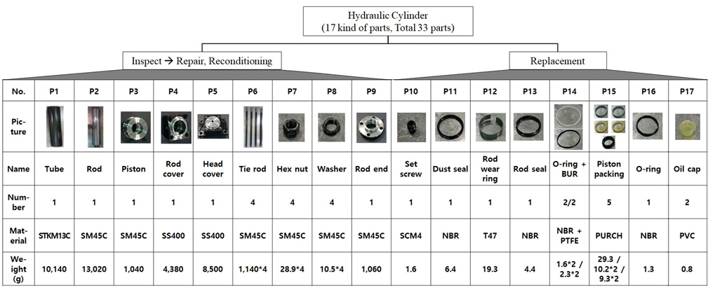
재제조 전 유압실린더 고품의 상태를 보면, 튜브의 경우 내외부 발청이 발생하고, 로드는 스크래치 및 찍힘이 있는 등 추력이 부족한 상태이며, 외부누유가 발생되어 본연의 기능을 수행 할 수 없는 상태였다. 유압실린더를 완전 분해 한 결과 Tube, Rod, Rod cover, 패킹류 등 17종 33개의 부품으로 구성되어 있으며, 정리한 결과는 Fig. 2와 같다. 부품 1~9번은 수리 및 조정을 통해 재사용이 가능하지만 부품 10~17번은 오링 및 패킹류로 부품특성 상 100% 교체가 필요하다.
2.2 유압실린더 재제조 공정분석
본 연구에서는 재제조 공정 중 해체와 재조립 공정을 중심으로 진행하였다. 해체와 재조립 공정 분석을 통해 Critical Process를 찾아내고 개선안을 도출하였다.
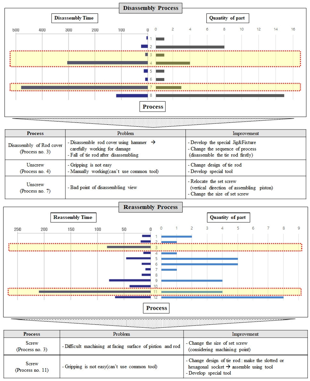
유압 실린더 해체/재조립공정 분석을 통하여 각 공정순서 별 부품 수, 공정 소요시간에 따른 상관관계를 도출해내고, 부품의 수에 비례하는 해체 시간을 가지는 공정, 부품의 수에 반비례하는 체결요소의 수를 가지면서 해체시간에 영향을 주는 공정 등을 분석하여 각 단위 공정의 문제점 및 개선안을 찾고 재제조 표준 공정 개발을 위한 데이터로 활용하였다. Critical 공정은 부품 수 보다는 공구의 접근성, 범용장비가 아닌 특수 공구의 필요성, 부품의 구조적 복잡성 등을 고려하여 도출하였다. 해체 및 재조립을 분석결과를 바탕으로 Critical 공정별 특징 및 문제점을 정의하고 이를 해결하기 위해 도출한 결과는 Fig. 3과 같다.
해체공정은 8개의 공정순서로 진행되며 총 970초의 작업시간이 소요되었다. 8개의 해체 공정 중에서 공정3(Rod cover 해체 : 해체부품의 고정이 어려움), 공정 4(Tie rod 해체 : 해체를 위한 잡힘점이 없음), 공정 7(Set screw 해체 : 공구의 접근성이 낮음)이 Critical 공정으로 나타났다.
재조립공정은 12개의 공정순서로 진행되며 총 616초의 작업시간이 소요된다. 12개의 재조립 공정 중에서 공정3(Set screw 체결을 위해 피스톤과 Rod의 접합면에 소형 나사산 가공 공정), 공정11(Tie rod 조립공정 : 체결을 위한 잡힘점이 없음)이 Critical 공정으로 나타났다.
2.3 유압실린더 FMEA
FMEA는 제품, 공정 등에서 발생 가능한 고장, 오류 등을 정의하고 관리함으로써 고장 위험을 사전 예방하고 고장 유형을 개선하는 기법이다[8]. FMEA 절차에 따라 유압실린더의 고장유형과 원인분석을 통하여 재제조 공정의 문제점을 파악하고 발생 가능한 단위공정에서 고장원인을 제거할 수 있는 개선안을 도출하여 표준공정개발에 적용하였다. 고장모드 분석을 위하여 유압실린더의 고장형태분석을 하였으며, 그 결과인 잠재적 고장형태, 고장의 잠재적 영향, 고장의 잠재적 원인을 Table 1에 나타내었다.
유압실린더의 고장형태로는 오링손상, 씰 및 패킹류의 손상, 실린더 외부손상, 피스톤 마모, 실린더 스틱슬립, 실린더 내부 손상으로 분석되었다.
여섯 가지 고장형태에 대한 심각도, 검출도, 발생도에 대한 전문가(관련 분야 5년 이상, 4명) 설문조사 결과와 고장형태분석 결과를 바탕으로 고장모드의 중요도를 결정하기 위하여 RPN (Risk Priority Number)을 산출하였다. 심각도, 검출도, 발생도는 6가지의 고장형태에 따라 설문조사를 통해 산출하였으며 일반적으로 RPN은 심각도(Severity) × 검출도(Detection) × 발생도(Occurrence)로 나타내며[4,9], RPN이 100 이상이면 문제점을 개선하기 위한 노력이 요구된다[10]. 산출 결과, O-ring 손상, Seal/Packing 손상 및 마모, 실린더 스틱슬립, 실린더 내부 파손이 RPN이 100 이상으로 나타났고 이들의 고장율을 낮추기 위한 개선안을 Table 2에 나타내었다.
3. 유압실린더 표준공정 개발
3.1 유압실린더 재제조 개선 공정
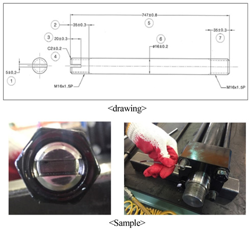
유압실린더의 해체/재조립 공정에서 가장 Critical Process는 Tie Rod의 해체 및 재조립으로 나타났다. 해체 및 재조립 용이성 향상을 위해 재설계한 Tie Rod의 형상을 Fig. 4에 나타내었다. Tie rod는 Rod cover와 Head cover 고정시키는 역할을 하는 부품으로 양 끝단에 나사산 가공되어 있는 환봉의 형태이다. 공구의 잡힘점이 없어 Tie Rod의 몸통을 잡고 작업이 이루어지므로 부품의 파손위험과 해체를 위한 힘의 전달력이 약하므로 해체가 용이하지 않다. 조립 및 해체용이성을 위해서는 공구를 사용하거나 공구의 분해/체결점을 명확히 하고 접근성을 높여 분해/체결력을 높여야 하므로[11], 이를 고려하여 Fig. 4와 같이 Tie Rod의 한쪽 끝단에 공구가 접근할 수 있는 홈(일자 형태)을 가공하였다.
샘플을 제작하여 해체/조립 실험한 결과 해체 공정시간 76% (305초 → 72초), 재조립 공정시간 75%(210초 → 52.5초)로 단축할 수 있었다. 초기 부품 가공 시 홈을 제작해야하는 가공공정이 추가되지만, 특수 공구가 필요 없이 범용 공구(드라이버, 렌치 등)로 쉽게 작업가능하며 해체 및 재조립 공정시간이 월등히 단축됨으로써 재제조 생산성 향상 및 유지보수에 효과적일 것이다.
3.2 유압실린더 재제조 표준공정 도출
단위공정 분석 및 FMEA 결과를 바탕으로 각 공정을 체계화하여 유압실린더 재제조 표준공정안을 정립하였다. Fig. 5와 같이 고품회수-고품분석-해체-세척-검사-수리 및 조정-재조립-성능평가의 8개 공정으로 분류하였으며 총 25개의 단위공정으로 구성된다. 세부 표준공정은 Table 3, 4, 5와 같다.
4. 유압실린더 재제조품 성능평가
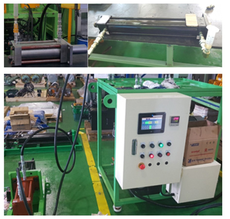
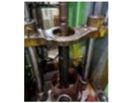
개발된 표준공정에 따라 재제조된 유압실린더의 성능평가를 RS B 0157 기준에 따라 테스트를 진행하였다. 재제조는 사용 후 혹은 폐기된 제품을 새 제품과 유사한 수준으로 제조 하는 것이기 때문에 기준 조건하 새 제품과 동등한 성능 구현여부를 테스트하였다. 성능평가 지표는 실린더 출력효율이며, 이를 위해 Fig. 6과 같이 테스트베드를 활용하여 성능평가를 하였다.
출력효율 시험방법은 시험 실린더와 부하 실린더의 사이에 부하측정 장치를 장착하여 최대 압력으로 작동시킨 후 출력효율을 측정하며 평가기준은 식 (1)의 출력효율이 90% 이상이어야 한다[12].
측정한 각 실린더의 출력값, 피스톤 면에 작용하는 압력, 유효 피스톤의 단면적을 식 (1)에 의해 실린더의 출력효율을 계산한 값을 Table 6에 나타내었다. 시험한 실런더의 출력효율이 모두 90%이상으로 나타나 기준에 만족하여 재제조된 유압실린더의 성능을 확인 할 수 있었다.
| (1) |
- F: Output of cylinder (kN)
- P: Pressure on face of piston (Mpa),
- A: Sectional area of piston (cm2)
5. 결 론
본 연구에서는 산업기계용 유압실린더의 재제조 표준화 공정 기술개발을 하였다. 이를 위해 먼저, 사출기용 유압실린더의 해체, 재조립 공정 중심으로 재제조를 수행하여 단위 공정을 분석하였다. 유압실린더 재제조의 해체 및 재조립공정을 중심으로 공정 및 고장모드 분석을 실시하였다. 그리고 고장유형 및 고장모드를 분석하고 이를 토대로 FMEA를 수행하여 Critical process에 대한 개선안을 도출하였다. 공정 및 FMEA 분석결과를 바탕으로 고품입고에서부터 성능평가까지 총 8단계의 재제조 공정을 분류하였으며, 이를 세분화하여 25개의 단위공정으로 구성된 유압실린더 재제조 표준공정도를 개발하였다. 제품수명이 종료된 유압실린더 고품을 재제조하여 출력효율에 대한 성능평가를 실시하여 평가기준(출력효율 : 90% 이상)을 만족함을 확인하였다. 개발된 표준 재제조공정을 통해 신품과 동등한 수준의 제품 재제조가 가능하고 체계화된 재제조 공정을 통해 공정시간이 2,556초에서 2,076초로 약 18.8% 단축되어 생산성을 높였다.
본 연구의 결과는 산업용 유압실린더의 재제조를 위한 표준화된 공정도를 제시함으로써 효율적이며 경제적인 재제조를 할 수 있는 가이드라인으로 활용될 것으로 사료된다.
Acknowledgments
이 논문은 부산대학교 기본연구지원사업(2년)에 의하여 연구되었음.
References
-
Yang, S. S., Ong, S. K., Nee, A. Y. C., (2016), A Decision Support Tool for Product Design for Remanufacturing, Procedia CIRP, 40, p144-149.
[https://doi.org/10.1016/j.procir.2016.01.085]

- Seo, Y. K., (2016), A Study on the Estimation of Durability Life Affected by Processing Dimension in Remanufacturing of Birfield Joint, A Thesis for a Doctorate, Chungnam National University, Republic of Korea.
- Park, B. G., (2017), FMEA Case Study for Remanufacturing ATC Performance Assurance, A Thesis for a Master, Changwon National University, Republic of Korea.
-
Ha, J. H., Woo, Y. S., Roh, Y. H., Lee, C. M., (2017), A Study on the Development of Standardization Technology for Remanufacturing Process of Used Vertical Machining Center, J. Korean Soc. Precis. Eng., 34(8), p517-524.
[https://doi.org/10.7736/kspe.2017.34.8.517]

-
Son, W. H., Park, S. J., Jeong, J. Y., Kim, J. H., Bin, H. W., Mok, H. S., (2016), Analysis of Throttle Body’s Remanufacturing Process and RPN, J. of Korean Inst. of Resource Recycling, 25(4), p11-22.
[https://doi.org/10.7844/kirr.2016.25.4.11]

-
Mok, H. S., Song, H. S., Kim, D. J., Hong, J. E., Lee, S. M., Ahn, J. T., (2014), Standard Process Design of Remanufacturing of LPG Vaporizer by Using FMEA, J. of Korean Inst. of Resource Recycling, 23(6), p54-62.
[https://doi.org/10.7844/kirr.2014.23.6.54]

-
S, Y. K., Jung, D. H., Yu, S. S., Rha, W. Y., (2016), The Optimization Study on the Test Method of Remanufactured Power Steering Oil Pump by Using FMEA, Transaction of the Korean Society of Automotive Engineers, 24(1), p90-98.
[https://doi.org/10.7467/KSAE.2016.24.1.090]

- Tracy Philip Omdahl, (1988), Reliability, Availability, and Maintainability Dictionary, Quality Press, USA.
- Kim, M. H., Jin, E. J., Park, G. M., (2013), Using Failure Mode and Effects Analysis to Design a Comfortable Automotive Driver Seat, Journal of Korea Multimedia Society, 16(1), p87-99.
- Mike, Kolich., (2014), Fault Tree Analysis and Fault Modes and Effect Analysis for Security Evaluation of IC Card Payment System, Applied Ergonomics, 45, p1087-1096.
- Mok, H. S., Han, C. H., Jeon, C. S., Song, M. J., (2008), Design Principle for Disassembly of Products, Transaction of the Korean Society of Automotive Engineers, 16(6), p48-57.
- RS, (2008), Compact Type Hydraulic Cylinder, RS B 0157, Republic of Korea.


